Auth
Document Metadata
Category: Customer Account Management / Authentication
Audience: Administrators, Engineers, Security Team
Difficulty: Intermediate to Advanced
Time Required: Approximately 45–90 minutes
Prerequisites: An active ConnexCS account with “Customer” module access; knowledge of SIP and/or IP authentication concepts
Related Topics: Customer – Main, Customer – Customer
Next Steps: Customer – Auth: IP / SIP User Authentication, Customer – Routing & Authentication Best Practices
Management Customer [Customer Name] Auth
Use the Auth tab to configure IP or SIP (Username / Password) Authentication for users.
Global IP and SIP Authentication
You can also configure and manage both IP and Session Initiation Protocol (SIP) Authentication for Customers and Carriers in Global IP Authentication or SIP User Authentication.
IP Authentication
When you enable IP Authentication, you link a customer switch's IP address to their account.
It involves verifying incoming traffic based on the source IP address.
This adds a layer of security by ensuring the calls are coming from a trusted source.
How it works
Matching IP Addresses: When a packet arrives from a specific IP address (e.g., 1.1.1.1), the system matches it to the corresponding customer.
Newly added IP immediately marked as Blocked under IP Authentication
This occurs because call requests were sent from the new IP before it's authorized. As a result, ConnexCS fraud detection in the firewall blocked the unauthorised IP. Attempted calls from this IP won't get completed.
To resolve the blocked IP, go to Setup Advanced Firewall. Select the blocked IP, then delete it from the firewall. This unblocks the IP, but it will take up to 15 minutes for the change to become active in the switch.
See Threat Detection for more details.
Enable IP Authentication
To enable, click next to IP Authentication:
Click each tab to view the configuration details
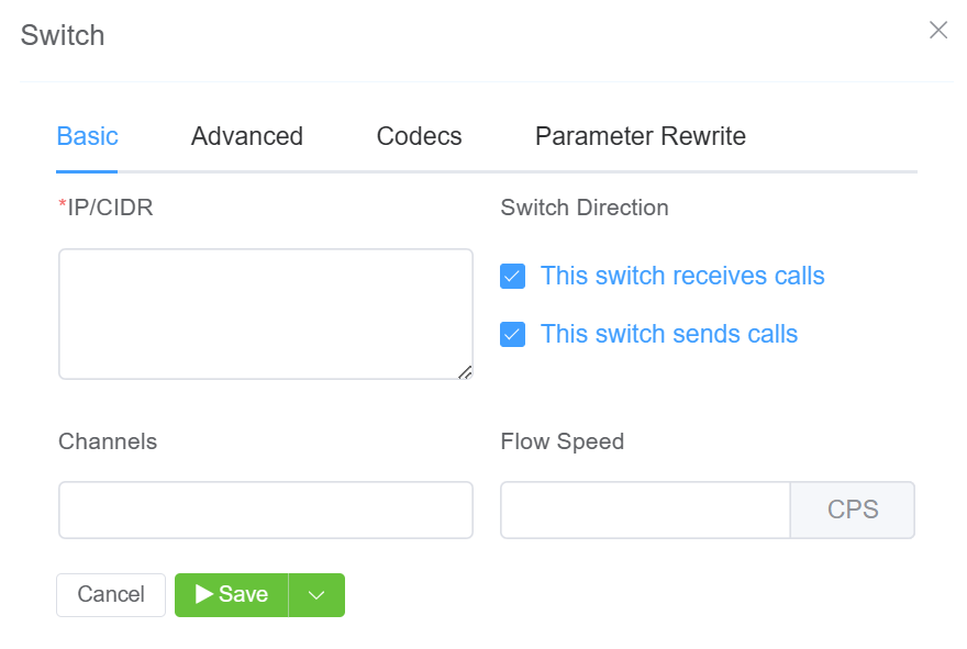
- IP/CIDR: Enter specific IPs or use CIDR notation to specify an entire subnet.
FQDN can be used for Ingress-only switches. You can assign multiple IPs. -
Switch Direction: The available options are from the perspective of the customer switch (PBX, dialer, etc), and describe how that switch interacts with the ConnexCS switch. For switches that send and receive calls from ConnexCS, there should be separate entries for each direction. Two types of switches are as follows:
This endpoint receives calls. This switch receives calls from ConnexCS. (Note: When selected, this gives the option of using the FQDN rather than the switch IP.)
This endpoint sends calls. This switch sends calls to ConnexCS.
-
Channels: Set the maximum number of concurrent calls for this switch.
-
Flow Speed: Set the Calls Per Second (CPS) (0 = unlimited calls).
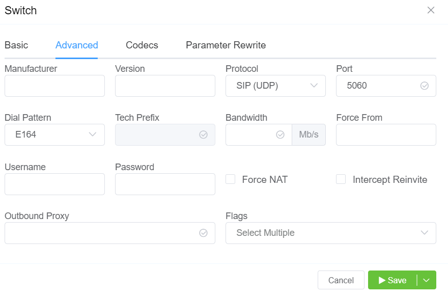
- Manufacturer and Version: These references fields allow you to enter the customer switch Manufacturer and Version, if required (these fields are not functional; they are informational only).
-
Protocol: Select the protocol for SIP (call signaling) and RTP (transport / audio).
UDP: SIP and RTP are unencrypted and transported over UDP.TCP: SIP is sent over TCP, RTP over UDP.TLS: SIP is sent over TLS (TCP), RTP over UDP.TLS & SRTP: SIP is sent over TLS (over TCP), RTP is encrypted with SRTP.SMPP: SMPP, for SMS, is not currently supported. -
Port: Default = 5060. If using TLS protocol, this should be set to 5061. ConnexCS is compatible with non-standard ports.
- Dial Pattern: The default selection is the industry standard.
- CLI Prefix, Tech Prefix, Force From: Do NOT Use these fields. Use the Parameter Rewrite tab to modify numbers.
- Username, and Password: Set when sending calls out (egress switch direction) to a remote system. Set this to allow the ConnexCS switch to operate as a client or UAC. Not typically recommended unless the customer has a very specialized system.
- Force NAT: Forces the switch to read the IP address the traffic was received from, not the IP in the SIP packet. (See Far-End NAT Traversal for more details on how ConnexCS handles NAT for SIP.)
- Intercept Reinvite: The only situation where this is recommended is when a customer's equipment doesn't support REINVITES. Enable this to correct issues with dropped calls by having ConnexCS respond to the INVITES, which can help keep calls up if they are being disconnected by the far-end switch.
- Outbound Proxy: Enter the IP address of a Proxy server for calls to route to before being sent to the carrier. This rewrites the UAC IP in the VIA field of the SIP header. This reduces management overhead as a customer only needs to authorize a single IP. Additionally, multiple addresses can be load-balanced using the AnyEdge system.
-
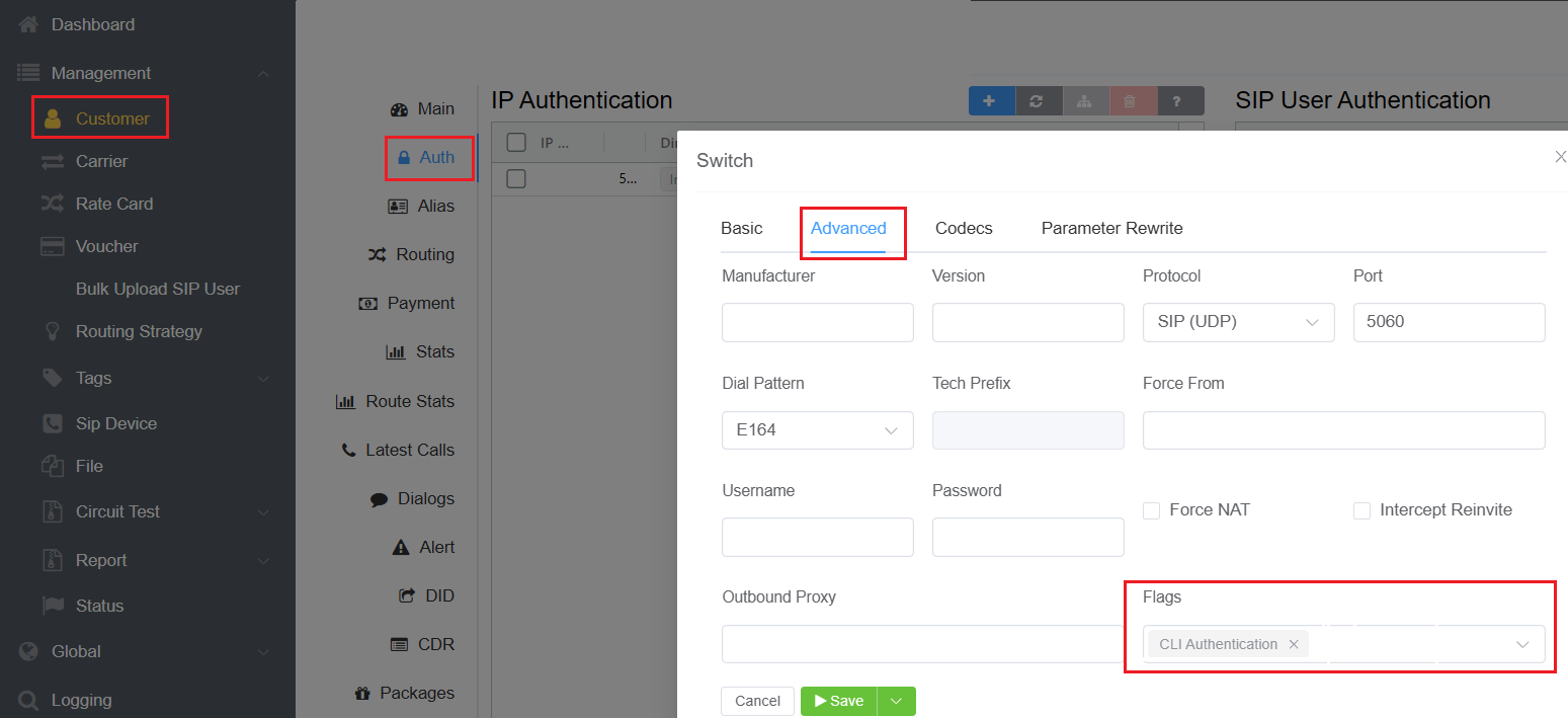
Flags: Check CLI Authentication flag for situations where Accounts are unable to use Tech Prefix to differentiate customers using the same IP. Check Disable NAT flag to disable NAT settings.
-
CLI Authentication: Select this flag to distinguish between multiple customers sharing the same IP address by using CLI Authentication instead of Tech Prefix.
-
Configuration
- CLI Routing: CLIs are used as a secondary authentication mechanism to identify which customer traffic belongs to.
Example
Joe and Bob share an IP address but have different CLIs; the system uses these CLIs to route calls correctly.
-
Setup Process
-
Configuring IP Authentication:
-
Navigate to Customer Customer [Name] Auth IP Authentication click on the blue
+sign. -
Under Advanced settings Flag Enable CLI Authentication.
-
This step ensures that the system will use CLI Authentication to differentiate customers with the same IP address.
-
-
-
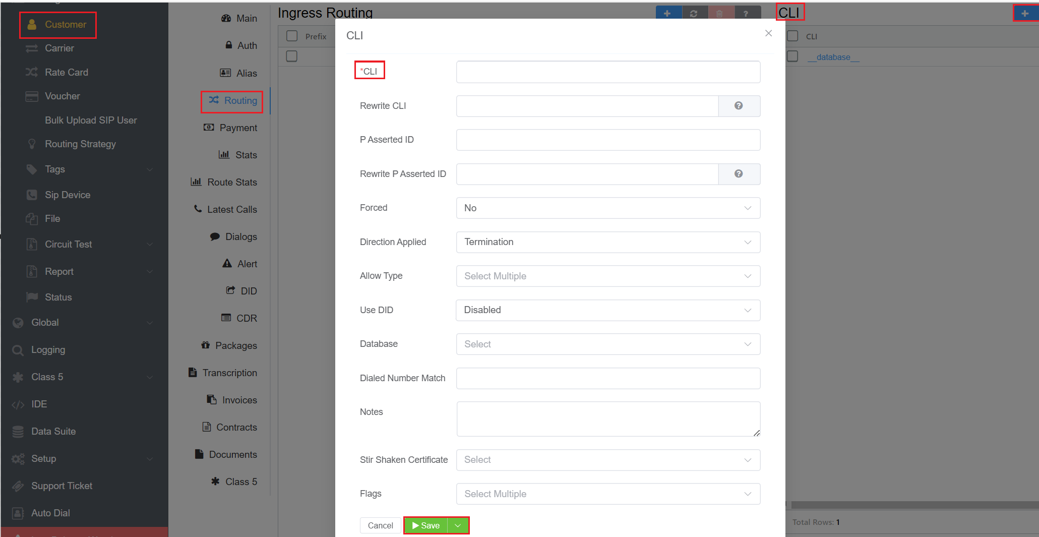
- Setting Up CLIs or Regular Expressions:
- Navigate to Customer Customer [Name] Routing CLI click on the blue
+sign. - Enter the specific CLIs, or Regular expressions associated with the customer.
- This configuration allows the system to match incoming call CLIs with the defined patterns.
- Navigate to Customer Customer [Name] Routing CLI click on the blue
-
Info
You can Use DID for CLI Authentication
Call Routing Logic
graph LR
A[Call Arrives] --> B{Check Source IP Address}
B --> |If the IP address matches with the entry in the Authentication configuration| C{Check CLI of the incoming call}
C --> |If both CLI and IP address match the configuration for a particular customer| D{Route Call to Customer}
Ensuring Consistent CLI Authentication Flag
Ensure that the CLI Authentication flag is consistently added to the IP configuration across all customers sharing the same IP address. This is crucial for the system to correctly apply the CLI-based routing logic.
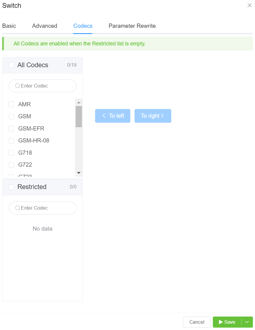
All Codecs are supported unless specifically set as Restricted here.
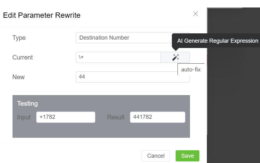
The Parameter Rewrite tab is used to manipulate data as it comes into the system, particularly useful for formatting phone numbers.
When and Why is it useful?
It is most useful when you need to create automatic replacements for destination numbers or CLI, so a number is formatted in the appropriate E164 format.
-
Configuration:
-
Number Formatting: Strip leading zeros or add country codes based on regular expressions.
Example: Changing 01782 to 441782 for international formatting.
-
Destination Number or CLI Manipulation: Apply these manipulations on either destination numbers or CLIs.
-
-
Steps for re-writing:
- Click
+. - Type: Select the parameter to modify.
- Current: Enter the prefix for the destination number, or the CLI. You also have the option to generate a regular expression using
AI Generate Regular Expression. - New: Enter what should replace the current information.
- Use the Testing
Inputfield to verify if the replacement is working as expected. - Click
Savewhen done. - If a parameter rewrite is already created, you will have the ability to test it from the main tab.
- Click
Example
International calls coming in with a + should be replaced with a specific country code.
Note
Click here to view an interactive IP address and CIDR range visualizer.
NAT Considerations
Network Address Translation (NAT): NAT can cause issues with SIP communications due to internal vs. external IP addresses.
- STUN (Session Traversal Utilities for NAT): Clients can use STUN to determine their external IP address and update SIP packets accordingly.
-
Application Layer Gateway (ALG): NAT devices can rewrite SIP packets to use external IP addresses, though this method is unreliable.
-
Far-end NAT Traversal: The system can detect and adjust for NAT by checking IP headers and assuming the correct external IP address.
SIP User Authentication
When you enable SIP Authentication, ConnexCS will reject the initial SIP INVITE with a "407 Authentication Required". This message includes a 'nonce' (a uniquely randomly generated hashed number). The customer switch will send appropriate authentication information to ConnexCS, which will connect the call. SIP Authentication involves using Usernames, Passwords and your Server's IP to authenticate SIP connections.
Generic SIP Trace showing the Challenge Response:

    sequenceDiagram
    autonumber
    Alice->>Bob: INVITE
    Bob-->>Alice: 100 Trying
    Bob->>Alice: 407 Proxy Authentication Required
    Note over Alice,Bob: 407 contains nonce.
    Note left of Alice: HASH(Combine Password + Nonce).
    Alice->>Bob: INVITE (+ Auth Header)
    Bob-->>Alice: 100 Trying
    Note right of Bob: HASH(Combine Password + Nonce).
    Note right of Bob: Compare Hashes - They Match.
    Bob-->>Alice: 183 Ringing
    Bob->>Alice: 200 OK (Connected)
For call authentication we should have a Username and a Password. The Username and Password should get to the other side.
The Username is sent on Plain-text and the user (Alice) hashes the password. 407 Proxy Authentication contains a nonce. A nonce is a random String of which gets send over to Alice. Both Alice and Bob are aware of this random string. Authorization header is sent with the INVITE. Then Bob combines the password with the nonce and compares the nonce. If the hashes match, the call gets connected.
407 Proxy Authentication is a part of Challenge-Response and is necessary when you proceed with SIP User Auth. Also you can't have IP Authentication and User / Password Authentication work together
UAC vs. UAS
UAC (User Agent Client): Acts as a client, typically used when sending calls out. UAS (User Agent Server): Acts as a server, typically used when receiving calls.
Enable SIP User Authentication
To enable, click next to SIP User Authentication:
Click each tab to view the configuration details
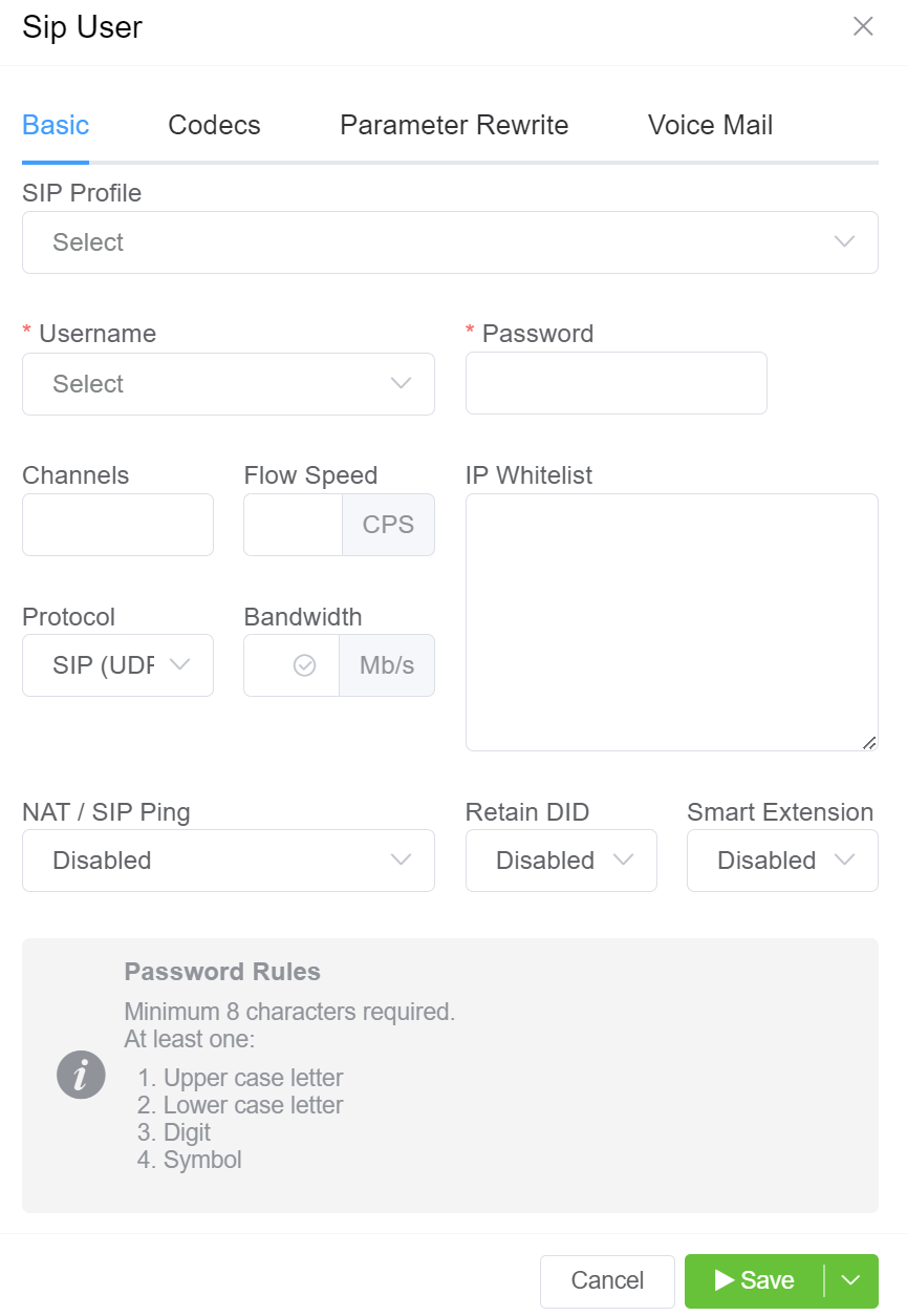
- SIP Profile: You can select the created SIP Profile here.
- Username: This will be the Username used for SIP authentication (must match configuration on the customer UAC). If the Customer has Internal Number Block set on the Main tab, you can only select the Username from available extensions. If a Username is already in use on the Account, they will get an error "Duplicate User Detected". Required when sending calls out to a remote system; the switch behaves in UAC (User Agent Client) mode.
- Password: Must match with the configuration on the customer UAC.
- Channels: Set the maximum number of concurrent calls for this switch.
- Flow Speed: Set the Calls Per Second (CPS) (0 = unlimited calls).
-
Protocol: Select the protocol for SIP (call signaling) RTP (transport/audio).
UDP: SIP and RTP are unencrypted and transported over UDP.TCP: SIP is sent over TCP, RTP over UDP.TLS: SIP is sent over TLS (TCP), RTP over UDP.TLS & SRTP: SIP is sent over TLS (over TCP), RTP is encrypted with SRTP.SMPP: SMPP, for SMS, is currently not supported. -
IP Whitelist: Applies to SIP Users used for sending or receiving call traffic.
- If IP whitelisting is configured:
- The SIP user may send calls only from the whitelisted IP address(es).
- Calls originating from non-whitelisted IP addresses will be rejected by ConnexCS.
- If no IP restriction is configured: Calls may be accepted from any IP address, subject to other authentication mechanisms.
- Purpose: This restriction protects against unauthorized traffic injection and fraud.
- If IP whitelisting is configured:
-
NAT/SIP Ping: Set behavior of pings sent from ConnexCS back to the customer through their firewall to their UAC. This helps when there are remote agents connecting to the switch. NAT/SIP Ping is used to keep the network address translation (NAT) open, ensuring calls can be received.
Disabled: No pings are sentEnabled: Send UDP pings every 60 seconds, helping to keep some longer calls (1800 or 3600 seconds) up.Enabled (Timeout): Send UDP pings every 60 seconds and disconnect the call (terminate registration) if the pings aren't returned.
How it works?
- When using NAT, outbound packets create a temporary port mapping.
- NAT remembers this mapping and routes responses back to the sender.
- UDP has no built-in KeepAlive, so NAT can close inactive ports.
- To prevent this, the system sends a SIP ping every 60 seconds.
- If no response is received, the system times out and deregisters the device.
graph TD
    A[Outbound Packet Sent] --> B[NAT Creates Temporary Port Mapping]
    B --> C[NAT Remembers Port Mapping and Routes Responses]
    C --> D[UDP Has No Built-in KeepAlive Mechanism]
    D --> E[NAT Can Close Inactive Ports After Timeout]
    E --> F[System Sends SIP Ping Every 60 Seconds to Keep Alive]
    F --> G{Check for Response from Device}
        G -- Yes --> H[Response Received, Continue Operation]
        G -- No --> I[No Response, System Times Out]
        I --> J[System Deregisters Device Due to Inactivity]
Common Issue
Outbound calls work, but inbound calls fail: This usually indicates a NAT issue where the port has closed. + Enabling NAT SIP Ping keeps the port open.
-
Retain DID: When you enable this, inbound calls will retain the destination number (DID), and the call is sent into the system, rather than using the SIP Username or routing calls to a predefined destination.
DID Setup
- DID:
+1234567890 -
Destination: Internal SIP User
TestRIS1 -
Behavior:
- Without Retain DID: Call to
+1234567890routes directly toTestRIS1. - With Retain DID: Call keeps
+1234567890as the destination, allowing further routing by downstream systems.
- Without Retain DID: Call to
- DID:
-
Smart Extension: It simplifies call transfers and enables advanced features like call barging and interception by centralizing REFER message handling within the Class 5 system. Unlike traditional SIP workflows, where the UAC or softphone manages transfers, this approach offloads complexity to us, enhancing functionality, user experience, and control through seamless integration of Class 4 and Class 5 systems.
-
Smart Extension Workflow:
graph TD %% Define node styles classDef startEnd fill:#d1e7dd,stroke:#0f5132,stroke-width:2px,font-weight:bold; classDef process fill:#f9f9c5,stroke:#d4a017,stroke-width:2px,font-weight:normal; classDef decision fill:#ffffcc,stroke:#999900,stroke-width:2px,color:#000,font-style:italic; %% Nodes A[UAC Initiates Call]:::startEnd B[Class 4 System Routes Call]:::process C{Upstream Carrier Determines Transfer Needed?}:::decision D[REFER Message Sent Back to Originating System]:::process E[Class 5 System Intercepts REFER Message]:::process F[Class 5 System Processes Transfer]:::process G[Class 5 System Initiates New Call]:::process H[New Call Flows to Class 4 System]:::process I[Call Routed to Updated Destination via Carrier]:::startEnd J[Call Continues Normally]:::process %% Links A --> B B --> C C -- Yes --> D D --> E E --> F F --> G G --> H H --> I C -- No --> J-
Advantages
-
Simplified Call Transfers: The complexity of handling REFER messages is shifted from the UAC to the Class 5 system. Ensures a seamless experience for the user, as the originating device is unaware of the transfer.
-
Advanced Call Manipulation: By routing calls through the Class 5 system, advanced features such as call barging, whispering, and interception are enabled.
Examples
- Call Barging: Useful in customer service scenarios where a supervisor might need to join an ongoing call to assist or guide the agent.
- Whispering: Ideal in training situations, allowing a mentor to provide instructions to the agent without the customer hearing.
- Interception: Crucial in security or compliance settings, enabling a manager to take over a call in progress if necessary.
- Centralized Complexity Management: Keeps call logic and transfer handling within the provider's infrastructure, reducing the burden on end-user devices.
Use Case Example
graph TD %% Define node styles classDef startEnd fill:#d1e7dd,stroke:#0f5132,stroke-width:2px,font-weight:bold; classDef process fill:#f9f9c5,stroke:#d4a017,stroke-width:2px,font-weight:normal; classDef decision fill:#ffffcc,stroke:#999900,stroke-width:2px,color:#000,font-style:italic; classDef normal fill:#f2f2f2,stroke:#666666,stroke-width:1px,color:#000; %% Nodes for With Smart Extension A1[UAC Calls 12345]:::startEnd B1[Class 4 System Routes Call]:::process C1{Upstream Carrier: Number Unavailable?}:::decision D1[Upstream Carrier Sends REFER Message]:::process E1[Class 5 System Intercepts REFER]:::process F1[Class 5 System Processes Transfer]:::process G1[Class 5 System Initiates New Call to 12346]:::process H1[New Call Flows Through Class 4 System]:::process I1[Call Routed to Updated Destination via Carrier]:::startEnd %% Links for With Smart Extension A1 --> B1 B1 --> C1 C1 -- Yes --> D1 D1 --> E1 E1 --> F1 F1 --> G1 G1 --> H1 H1 --> I1 %% Nodes for Without Smart Extension A2[UAC Calls 12345]:::startEnd B2[Class 4 System Routes Call]:::process C2{Upstream Carrier: Number Unavailable?}:::decision D2[Upstream Carrier Sends REFER Message]:::process E2[UAC Receives REFER Message]:::process F2[UAC Handles Transfer:Potential Failure]:::normal G2[UAC Initiates New Call to 12346]:::normal H2[New Call Flows Through Class 4 System]:::normal I2[Call Routed to Updated Destination via Carrier]:::startEnd %% Links for Without Smart Extension A2 --> B2 B2 --> C2 C2 -- Yes --> D2 D2 --> E2 E2 --> F2 F2 --> G2 G2 --> H2 H2 --> I2 %% Subgraphs (optional for grouping) subgraph With Smart Extension direction LR A1 --> B1 --> C1 --> D1 --> E1 --> F1 --> G1 --> H1 --> I1 end subgraph Without Smart Extension direction LR A2 --> B2 --> C2 --> D2 --> E2 --> F2 --> G2 --> H2 --> I2 end %% Notes outside of subgraphs I1 --> |Note:| N1["Seamless Transfer"]:::normal I2 --> |Note:| N2["Complexity and Potential Failures"]:::normal -
-
-
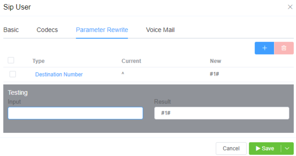
All Codecs are supported for the SIP user unless specifically set as "Restricted" here.
The Parameter Rewrite tab is used to manipulate data as it comes into the system. It is most useful when you need to create automatic replacements for destination numbers or CLI, so a number is formatted in the appropriate E164 format.
-
Click
+. -
Type: Select the parameter to modify.
- Current: Enter the prefix for the destination number, or the CLI. You also have the option to generate a regular expression using
AI Generate Regular Expression. - New: Enter what should replace the current information.
- Use Testing
Inputfield to verify if the replacement is working as expected. - Click
Savewhen done. - If a parameter rewrite is already created, you will have the ability to test it from the main tab.
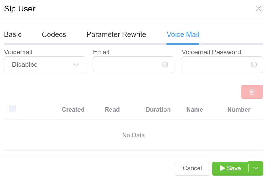
If you enable Voice Mail, you can set which email address receives messages, reset the Voicemail Password, and view and delete current messages.
Key Features:
-
Enable voicemail for specific extensions.
-
Configure email notifications for new voicemails.
-
Set up a voicemail password for retrieval.
-
To access voicemail, dial *1 (subject to routing settings).
See Voicemail for information on accessing Voicemail.
Duplicate IP Detection & Warning
Our system generates a warning notification if a duplicate IP address is detected.
Additional Considerations
- Re-invite Mechanism:
- Used to maintain active calls by sending periodic invite messages to reestablish the call state.
- Helps in managing timeouts and ensuring that both sides of the call are aware of its status.
- Intercept Re-invite:
- Used in scenarios where customers' equipment can't handle re-invites properly; the system intercepts and responds on behalf of the customer.
Channel Capacity Limitation
Overview
The Channel Capacity Limitation feature allows administrators to control the maximum number of channels available to each customer account. It efficiently manages channel resources across multiple SIP users, ensuring the account stays within its allocated capacity.
How It Works?
- Channel Allocation in Control Panel:
- Each customer account is assigned a maximum number of channels via the control panel.
-
The total channel allocation is the upper limit for all SIP users within the account.
-
Channel Assignment for SIP Users:
- Customers can create multiple SIP users through the customer portal. During setup, the customer allocates a specific number of channels to each SIP user.
-
The sum of channels assigned to all SIP users can't exceed the account’s total channel capacity.
-
Error Notification:
- When the customer attempts to allocate more channels than their account limit allows, they will receive an error message: "No channel capacity available for your account."
- This message indicates that the requested channel allocation for the SIP user exceeds the remaining available channels in the account.
flowchart TD
    A[Channel Allocation in Control Panel] --> B[Assign Maximum Number of Channels to Customer Account]
    B --> C[Upper Limit for All SIP Users Combined]

    C --> D[Channel Assignment for SIP Users]
    D --> E[Create Multiple SIP Users in Customer Portal]
    D --> F[Allocate Channels to Each SIP User]
    F --> G[Check if Sum of Channels <= Account's Total Capacity]

    G -->|Yes| H[Channels Successfully Assigned]
    G -->|No| I[Error: No channel capacity available for your account]

    I --> J[Requested Allocation Exceeds Remaining Available Channels]
Example Use Case
- A customer account has a channel allocation of 100.
- The customer creates two SIP users, each assigned 50 channels.
- If the customer creates a third SIP user and assigns even one additional channel, an error occurs because the 100-channel limit is reached.
flowchart TD
A[Customer Account] -->|Allocated 100 Channels| B[Create SIP User 1]
A -->|Allocated 100 Channels| C[Create SIP User 2]
B -->|Assign 50 Channels| D[Total Used: 50 Channels]
C -->|Assign 50 Channels| E[Total Used: 100 Channels]
F[Attempt to Create SIP User 3] -->|Allocate 1+ Channels| G[Error: Total Capacity Reached]
D --> E
E --> F
Benefits
- Resource Control: Ensures that channel usage is kept within limits, preventing over-allocation.
- Improved Customer Management: Customers understand channel limitations, promoting efficient SIP user configuration management.
- Error Prevention: Proactively blocks configurations that would exceed the account's channel capacity. It helps to avoid unexpected issues in the SIP user setup.
Recommendations
- Channel Reallocation: Customers can modify channels allotted to current SIP users to free up space.
- Capacity Upgrades: Customers can request a channel increase if their needs exceed the initial limit.
This feature ensures precise control and optimization of channel resources for manageable SIP user configurations across all accounts.
Reset SIP Password
Click the Password key next to the SIP user to reset the password.
You can also use Generate Password to generate a random and secure SIP password.
Make sure you Copy Text and provide this information for configuration, as this password can't be retrieved after it's set.
Customers using the Customer Portal can reset their SIP Passwords in Authentication.
SIP Password security
SIP passwords are needed for the SIP protocol, but they can present security risks for a provider.
You must configure them in ConnexCS when SIP authentication is setup, but they aren't available for providers to retrieve later.
Providers should generate a unique SIP password for each SIP user and send that to the customer. This gives the customer the responsibility of keeping track of the password and keeping it safe.
Additionally, the unique password will allow for traceability if the customer's system is ever compromised.
Send message to SIP Users
Use Send next to the SIP User to send a SIP message to the end device which will flash on the phone.
Users can't reply to messages.
SIP Pings
Case 1: Normal SIP Ping
    sequenceDiagram
    autonumber
    Alice->>Bob: INVITE (cseq 1)
    Bob-->>Alice: 100 Trying
    Bob-->>Alice: 183 Ringing
    Bob->>Alice: 200 OK (Connected)
    Alice->>Bob: ACK
    Note over Alice,Bob: The call is active
    Bob->>Alice: OPTIONS
    Alice->>Bob: 200 OK
    Note over Alice,Bob: The call has ended
    Alice->>Bob: BYE
    Bob->>Alice: 200 OK
In this case, Bob sends a message to Alice called OPTIONS and Alice sends back 200 OK. If 200 OK isn't sent, the call be get disconnected.
Case 2: Alice Disappears
Use Case for NAT/SIP Pings
Troubleshooting Scenario The Customer reports they can register and make outbound calls, but they're unable to receive inbound calls.
What's happening In a typical configuration, a packet is sent from the customer UAC out through a NAT/firewall, and then the packet gets delivered to the UAS:
    graph LR
    A(Customer switch) --> B(NAT/firewall)
    B --> C(ConnexCS switch)
    style A fill:#ECEFF1,stroke:#4051b5,stroke-width:4px
    style B fill:#ECEFF1,stroke:#4051b5,stroke-width:4px
style C fill:#ECEFF1,stroke:#4051b5,stroke-width:4px- When a packet goes out, a hole gets punched in the firewall, and the source port gets recorded. When a packet returns on that port, the firewall knows to deliver back to the UAC.
- This works well when using TCP, which sends regular keep-alive packets.
- UDP doesn't send keep-alives (no connected state as with TCP). SIP does maintain a connected state, registration, but may have long periods of inactivity.
- Without regular traffic passing between UAS and UAC in the form of keep-alives/registration (a normal occurrence), NAT will eventually time out and shut down the connection.
- Enabling UDP or SIP pings can show the NAT/firewall that the signaling path is still valid and in use.
How NAT/SIP Ping measures Latency
- A SIP ping request is sent to the User Agent Client (UAC).
- When a response is received, the system calculates latency.
- Useful for diagnosing VoIP quality issues.
- Can help troubleshoot high latency due to poor mobile network connections.
graph TD
A[SIP Ping Request Sent to UAC] --> B[UAC Receives Request]
    B --> C[UAC Sends Response Back]
    C --> D[System Receives Response]
    D --> E[Calculate Round-Trip Time-RTT Latency]
        E --> F[Latency Calculated]
            F --> G{Evaluate VoIP Quality}
                G -- High Latency --> H[Troubleshoot Poor Mobile Network Connections]
                    H --> J[Adjust Network Settings or Contact Provider]
                G -- Normal Latency --> I[Continue Normal Operation]