Open Systems Interconnections Model
Document Metadata
Category: Infrastructure & Transport / Networking Fundamentals (OSI Model)
Audience: Administrators, Network Engineers, Support Team
Difficulty: Intermediate (networking knowledge recommended)
Time Required: Approximately 20–30 minutes
Prerequisites: Basic understanding of network layers, familiarity with VoIP signaling & media flows
Related Topics: OSI Model Layers Overview, Latency Types in VoIP Context
Next Steps: After reviewing the OSI model and how it applies to call-signaling and media flows, map your system architecture against each layer (Physical → Application) to identify potential fault locations and set up monitoring/alerts at relevant layers (for example, link latency at Layer 1/2, routing issues at Layer 3/4, SIP signaling at Layer 5/7) using the monitoring tools in the platform.
Computer systems interact via networks using 7 layers, as described by the OSI model.
In the 1980s, all significant computer and telecommunications companies accepted it. It's the first industry standard for network communications.
In the year 1984, the International Organization for Standardization (ISO) created OSI. It has a 7-layer architecture, with each layer carrying out a particular duty. To transport data from one person to another across the world, all 7- layers must work together.
Open Systems Interconnections Model Layers
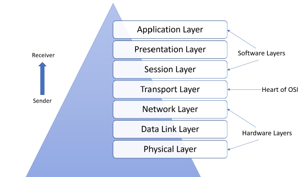
Physical Layer
It's in charge of the wired / wireless connections that physically connect network nodes.
It specifies the connection / electrical cable / wireless technology that connects the devices.
It regulates the bit rate and the transmission of the raw data, which is just a stream of 0s and 1s.
Data Link Layer
It creates and breaks connections between two network nodes.
Packets get disintegrated into Frames, which are then sent from the source to the destination.
This layer comprises of 2 components: Media Access Control (MAC), and Logic Link Control (LLC).
MAC utilises MAC addresses to link devices. It establishes permissions to send and receive data.
LLC identifies network protocols, does error checking, and synchronises frames.
Network Layer
The network layer serves two primary purposes. One is dividing segments into network packets, which are then put back together at the other end. The other is packet routing with the best route. To route packets to a target node, the network layer needs network addresses (IP addresses).
Transport Layer
Data sent at the session layer gets divided into "segments" by the transport layer. It happens at the receiving end.
On the receiving end, it's in charge of putting the segments back together. It provides data that the session layer may use.
The transport layer performs error control. It determines if data gets transmitted at an incorrect rate.
It also performs flow control. It checks if data gets transmitted at the same rate as the receiving device.
Session Layer
The session layer creates communication channels, called sessions, between devices. It's responsible for opening sessions. It ensures the sessions remain open and functional while data is getting transferred. It also closes the sessions when communication ends.
This layer can set checkpoints during a data transfer for any session interruption.
Devices can resume data transfer from the last checkpoint.
Presentation Layer
The presentation layer prepares data for the application layer. It defines how two devices should encode, encrypt, and compress data. It's done so that the received data correctly on the other end.
The presentation layer takes the data transmitted by the application layer and prepares it for transmission over the session layer.
Application Layer
End-user applications like web browsers and email clients operate at the application layer.
It offers protocols that let computer programs send and receive data.
Network Latency, Application Latency and SIP Latency
1.Network Latency refers to the delay in data transmission over a network. It's the time taken for data to travel from the source to the destination through the network infrastructure.
| Components | Description |
|---|---|
| Propagation Delay | Time taken for a signal to travel through the physical medium, for example fiber optic cables, wireless links etc |
| Transmission Delay | Time required to transmit a packet of data over the network |
| Processing Delay | Time spent by routers and switches processing packets |
| Queueing Delay | The time packets spend waiting in queues at network devices |
| Causes | Explanation |
|---|---|
| Distance | Signals travel faster over shorter distances |
| Network Congestion | High traffic can cause delays as packets wait in queues |
| Network Quality | Poorly maintained or low-quality networks can introduce additional latency |
| Protocol Overhead | Additional overhead from network protocols like TCP/IP can add to latency |
Examples
- A user accessing a website hosted on a server located on the other side of the world may experience higher network latency due to the longer distance the data needs to travel.
- Video streaming services may suffer from network latency, causing buffering or lag.
2.Application Latency refers to the delay between when an application receives a request and when it responds with the requested data or action. It includes all processing steps within the application itself, excluding network transmission times.
| Components | Description |
|---|---|
| Server Response Time | Time taken by the server to process the request and generate a response |
| Database Query Time | If the application relies on databases, this includes the time taken to execute queries and retrieve data |
| Computation Time | Time spent on computational tasks such as data processing, algorithm execution, etc |
| Resource Allocation | Time spent allocating resources like memory, CPU cycles, etc |
| Causes | Explanation |
|---|---|
| Server Load | High server load can slow down response times |
| Database Performance | Slow database queries can significantly impact application latency |
| Code Efficiency | Inefficiently written code can lead to longer processing times |
| Resource Constraints | Limited resources such as RAM or CPU power can cause delays |
Example
- A web application that takes several seconds to load a page after clicking on a link is experiencing high application latency.
- A mobile app that takes a long time to process user input (e.g., logging in) is suffering from application latency.
3.SIP Ping Latency refers specifically to the delay in sending and receiving SIP messages, which are used in VoIP and other real-time communication services. This type of latency is crucial for ensuring timely and reliable communication.
| Components | Description |
|---|---|
| SIP Message Transmission | Time taken for SIP messages (e.g., INVITE, ACK, BYE) to be transmitted between endpoints |
| Server Response Time | Time taken by SIP servers to process and respond to SIP requests |
| Causes | Explanation |
|---|---|
| Network Latency | Underlying network conditions can affect SIP message transmission times |
| Server Load | High load on SIP servers can slow down response times |
| Configuration Issues | Mis-configured SIP settings or firewalls can introduce delays |
Examples
- In VoIP calls, high SIP ping latency can cause delays in call setup and tear-down, leading to poor user experience.
- In video conferencing, delayed SIP messages can result in synchronization issues between audio and video streams.
Relationships Between Latency Types
-
Network Latency affects both SIP ping latency and Application latency because it influences how quickly data (including SIP messages and application requests) can be transmitted over the network.
-
Application Latency can be influenced by both network latency (for data transmission) and server-side processing times. High network latency can exacerbate this by delaying the transmission of requests and responses.
-
SIP Ping Latency is particularly sensitive to underlying network conditions. Therefore, high network latency will directly impact SIP ping latency.
Important Note
SIP Ping Latency= Network Latency + Application Latency
Summary
-
Network Latency measures data travel delay.
-
Application Latency is primarily server-side processing delay, independent of network transmission times.
-
SIP Ping Latency combines network latency and SIP server processing delays.
VoIP Latency
The time delay between the time a voice packet gets delivered and when it arrives at its destination is latency in VoIP.
For VoIP conversations, a delay of 20 ms is common. A latency of up to 150 ms is perceptible and hence acceptable. But once you get over that, the quality starts to suffer. When it reaches 300 ms or more, it's unacceptable.
VoIP call quality gets affected by high latency, leading to:
- Slow and interrupted phone conversations
- Conflicting and overlapping noises
- Echo
- Disruption of speech and other data type synchronization, notably during video conferencing